NSX-T (SDN)

Warning !
work in progress : content under review, subject to change
Cloud Avenue networking services are powered by VMware NSX-T, providing Software-Defined Networking (SDN) capabilities for tenant connectivity, network segmentation and routing.
NSX-T also provides the platform’s firewall capabilities. While this section focuses on networking services and architecture, security and firewall features are described in the Security section of this documentation.
The NSX-T architecture is built around two complementary gateway layers :
Tier-0 Gateway (T0)
The Tier-0 Gateway is a provider-managed component that delivers connectivity between customer environments and external services.
Each customer benefits from a dedicated routing context on the shared Tier-0 infrastructure.
The Tier-0 Gateway provides access to external networks and services, including:
- Internet connectivity
- BVPN Galerie connectivity
- Cross Connect services
- Management and administration networks
- Shared platform services
The Tier-0 Gateway is fully configured and managed by the Cloud Avenue platform. No customer intervention is required.
Tier-1 Gateway (T1)
The Tier-1 Gateway is dedicated to the customer environment and acts as the networking entry point for the Virtual Data Center (vDC).
It provides routing and networking services for tenant workloads and enables the creation and management of:
- Routed networks
- Isolated networks
- Network Address Translation (NAT)
- DHCP services
- Static routing
- Load balancing services (where applicable)
- VPN services (where applicable)
The Tier-1 Gateway configuration is managed directly by the customer through the VMware Cloud Director portal. *
Gateway Sizing
Cloud Avenue offers several gateway sizes to accommodate different workload requirements and network throughput expectations.
Gateway sizing directly impacts the available networking capacity and should be selected according to both current and anticipated future requirements.
Typical sizing considerations include:
- Expected network throughput
- Number of virtual machines
- Number of connected networks
- NAT and routing requirements
- VPN usage
- Future growth projections
Important: Gateway resizing is not an in-place operation. Moving from one gateway size to another requires the recreation and reconfiguration of the networking environment. Customers should therefore carefully evaluate their requirements and select the appropriate gateway size during the initial design phase.
The available gateway sizes and their associated throughput limits are described in the following sections.
NSX-T gateways specifications
Depending on the needs, several configurations are available.
| Type of gateway | Class of service | Specifications |
Connected networks (recommandation) |
| T0 VRF | Standard | 300 Mbps max flow(*) |
|
| T0 VRF | Premium | 1 Gbps débit max (*) |
|
| Dedicated T0 | Medium | 3,5 Gbps max flow(*)
|
|
| Dedicated T0 | Large |
|
|
| T1 | Standard | 300 Mbps max flow (*)
|
A single interface for connection to the T0
|
| T1 | Premium | 1 Gbps max flow (*)
Need a T0 Premium |
|
| Dedicated T1 | Medium | 3.5 Gbps max flow (*)
Need a dedicated T0 Medium |
|
| Dedicated T1 | Large | 7 Gbps max flow (*)
Need a dedicated T0 Large |
Interconnection
The VDR and CHA Data Centers are interconnected by a resilient L3 VXLAN infrastructure with multiple low-latency 100Gb/s links (WDM) between the sites.
Cloud Avenue has four dedicated 25Gb/s links provided by this underlying infrastructure.
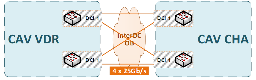
The latency between the two Cloud Avenue sites is less than 5ms.
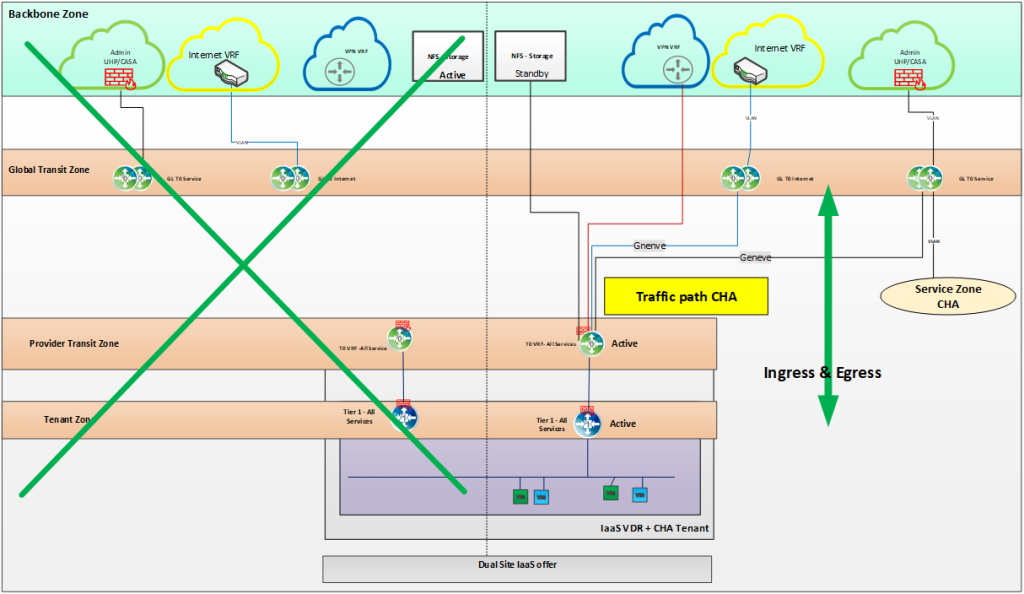
Network Architecture Overview
The platform is deployed across two geographically separated sites in a dual-site topology, with the network layer operating in an active-passive configuration.
Network Gateway Design
All north-south (ingress/egress) traffic is routed through the primary site using the VDR network as the default gateway.
The VDR network serves as the default gateway for all tenant/workload networks, ensuring consistent routing policy enforcement and traffic control.
Failover Mechanism
In the event of a primary site failure (planned or unplanned), gateway failover is automatically triggered toward the secondary (CHA) site.
This includes
- Re-establishment of routing adjacencies
- Activation of the standby gateway instance
- Traffic redirection to the CHA site
The failover process is designed to minimize convergence time and ensure continuity of north-south traffic flows with limited packet loss and acceptable recovery time objectives (RTO).
Disaster Recovery
If one site fails, services continue to operate from the other site without requiring a separate DR environment.
Disaster recovery is built into the design through the dual-site setup.