Network
Overview
The network and security layer of Cloud Avenue is provided by the NSX-T solution from vmware. The implementation is performed at two levels:
- a T0 Edge gateway, including a per-customer dedicated context, able to connect to the external networks: internet, BVPN Galery,Cross Connect, administration, etc. The T0 Edge gateway configuration is done automatically by the platform.
- a T1 Edge gateway, able to manage the vDC networks, whom configuration is done by the Customer from the vCloud Director portal.
The IP address ranges are chosen by the Customer, generally among non-routable subnets.
NSX-T gateways specifications
Depending on the needs, several configurations are available.
| Type of gateway | Class of service | Specifications |
Connected networks (recommandation) |
| T0 VRF | Standard | 300 Mbps max flow(*) |
|
| T0 VRF | Premium | 1 Gbps débit max (*) |
|
| Dedicated T0 | Medium | 3,5 Gbps max flow(*)
|
|
| Dedicated T0 | Large |
|
|
| T1 | Standard | 300 Mbps max flow (*)
|
A single interface for connection to the T0
|
| T1 | Premium | 1 Gbps max flow (*)
Need a T0 Premium |
|
| Dedicated T1 | Medium | 2,5 Gbps max flow (*)
Need a dedicated T0 |
|
| Dedicated T1 | Large | 6 Gbps max flow (*)
Need a dedicated T0 |
(*) The max flow means the global throughput available for the gateway.In software-defined networking environments, it is normal to observe a small difference between the bandwidth profile value and the throughput measured by end-to-end tools such as iPerf. This can be influenced by protocol/encapsulation overhead and traffic shaping behavior.
As an example, for a 300 Mbps profile, a measured TCP throughput around 270–290 Mbps may be within the expected range. In addition, TCP mechanisms (slow start / congestion window) and test conditions (test duration, number of streams, MTU) can impact the measured value.
All the gateways are in high availability mode by default. The max flow information is given according to a network packet size of 1500 bytes.
By default, the T0 VRF and T1 gateways are hosted on a mutualized cluster. It is possible to order a dedicated T0 & T1 (hosted on a dedicated VM cluster), for the following use cases:
- huge need of internet bandwidth
- organization with a lot of vDCs and several hundred VMs
- Customer preference for dedicated component (in addition to a dedicated cluster for example)
- need to manage a lot of T0 VRF
Upgrade
The transition from a standard T0 VRF gateway to a Premium T0 VRF or from a Premium T0 VRF gateway to a dedicated T0 requires planning and results in a service interruption.
The NSX configurations
General case
With this architecture, the Internet or VPN Gallery bandwidth subscribed by the Customer for each Organization is configured at the T0 level, and shared between the different vDCs.
A T1 gateway is used to create Organization networks that can be shared between all vDCs in the Organization.
Each T1 can be connected to a single T0 gateway, with a single interface.
In the diagram presented here, a T0 VRF gateway is subscribed by default and will manage all the underlying networks distributed by the T1 at the vDC level.
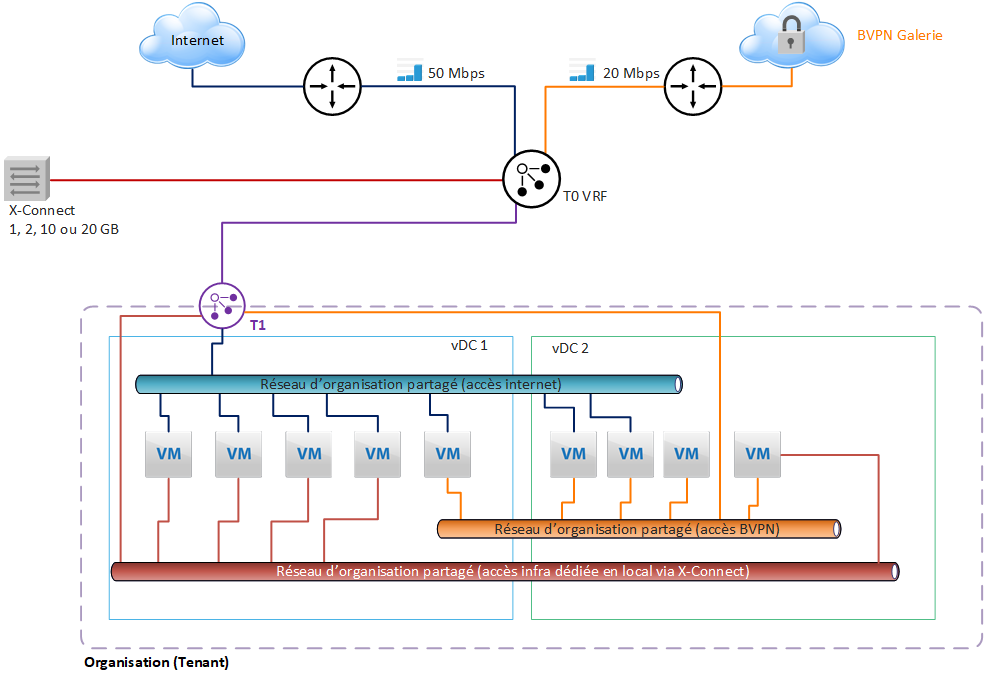
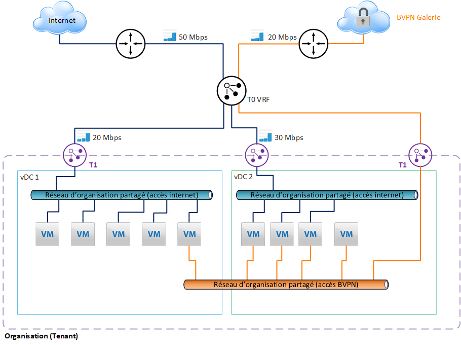
Internet bandwidth limitation
The Customer may limit the bandwidth of a T1 gateway. This makes it possible to control the sharing of bandwidth between the different vDCs.
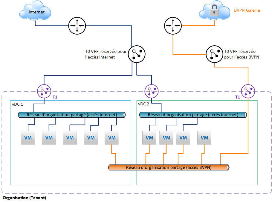
Configuration with 2 T0 VRF
To meet internal security policy constraints, it is possible to separate the external networks and assign them a separate T0 VRF.
In our example, we have assigned a T0 VRF for internet access, and another T0 VRF for access to the BVPN Gallery.
This separation is recommended to avoid configuration errors made by the customer, which would lead to exposing networks or VMs on the internet that should not be exposed. Indeed, the configuration of each external network will be done in 2 different gateways in VCD.
Note that if the Customer needs to manage a lot of T0 VRF, he must consider the dedicated T0 option, which can provide up to 100 T0 VRF.
Integrated features
Organization networks
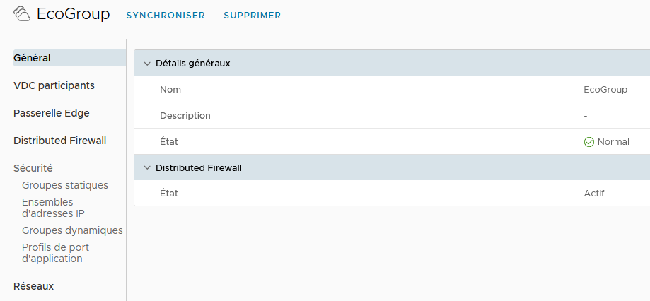
The Edge T1 gateway is used to create the internal networks of the vDC on which the VMs will be connected. The addressing of these networks is chosen by the Customer during configuration/creation. To share the networks between vDCs, it is necessary to create a group of vDCs, in order to include the vDCs concerned, which can then share the functionalities of the Edge gateway T1, and its networks.
Firewall
The T1 gateway offers a 2-level firewall:
- perimeter firewall, for north-south flows, i.e. entering and leaving the vDC (or group of vDCs)
- distributed firewall, for east-west flows, on a scope ranging from a single vDC to all the vDCs included in a group of vDCs.
Perimeter firewall configuration will be done in the Services options of the T1 Edge Gateway configuration. All incoming and outgoing flows of the vDC will be filtered through the rules implemented here. It will also be possible to configure a point-to-point IPSec VPN between the remote equipment and the Edge T1 gateway.
A Load Balancer is also available, providing basic functionality for clustering servers.
The Security option will allow you to manage part of the configuration related to the distributed firewall. This is where you need to define the security groups that carry the authorizations defined later in the firewall configuration (see below).
IP Address Management allows you to configure advanced T1 Edge Gateway IP services, such as DNS or DHCP forwardin
In the vDC group configuration, we will be able to configure the distributed firewall, and define fairly fine-grained permissions at the security group level.
This extremely powerful feature allows:
- effectively protect VMs by filtering east-west flows
- to create trust zones based on tags manually positioned on the VMs or built dynamically from programmed rules.
All features described below are configurable by Customer in the vCloud Director portal.
LBaaS ( Load Balancer as a Service)
Overview
The load balancer service in Cloud Avenue is provided by VMware’s NSX Advanced Load Balancer (NSX ALB) solution.
The implementation is carried out at the T1 gateway level in a vDC or a “Data center group ” (i.e., a group of multiple vDCs) if they are connected to the same T1 gateway within the same AZ (Chartres or Val de Reuil).
You can create/manage the load balancer configurations from the tenant user interface (vCloud Director – VCD portal).
Advanced Load Balancer – Shared and Dedicated
The load balancer services available on Cloud Avenue IaaS are as follows :
| Type of LBaaS | Configuration Requirements | Load Balancing Engine Resilience | Load Balancing Engine Resilience |
| Shared | T0 VRF Premium | 20 VIP | Active / Standby Active / Active |
| Dedicated | T0 VRF Premium | 200 VIP | Active / Standby Active / Active |
The load balancer services available on Cloud Avenue IaaS are as follows :
| Type of LBaaS | Configuration Requirements | Quota de classe de service par défaut | Résilience du moteur de Load Balancing |
| Dédié | T0 Dédié Medium | 200 VIP par Service Engine | Actif / Standby Actif / Actif |
| Configuration Parameters | IaaS with vDC | IaaS with vCoD | |
|---|---|---|---|
| Application Type | HTTP | ▲ | ▲ |
| HTTPS | ▲ | ▲ | |
| L4 TCP | ▲ | ▲ | |
| L4 UDP | ▲ | ▲ | |
| L4 TLS | ▲ | ▲ | |
| Load Balancing Algorithm | Least Connections | ▲ | ▲ |
| Round Robin | ▲ | ▲ | |
| Consistent Hash | ▲ | ▲ | |
| Fastest Response | ▲ | ▲ | |
| Least Load | ▲ | ▲ | |
| Fewest Servers | ▲ | ▲ | |
| Random | ▲ | ▲ | |
| Fewest Tasks | ▲ | ▲ | |
| Core Affinity | ▲ | ▲ | |
| Pool Persistence | Client IP | ▲ | ▲ |
| HTTP Cookie | ▲ | ▲ | |
| Custom HTTP Header | ▲ | ▲ | |
| Application Cookie | ▲ | ▲ | |
| Client IP | ▲ | ▲ | |
| Active Health Monitor | HTTP | ▲ | ▲ |
| HTTPS | ▲ | ▲ | |
| TCP | ▲ | ▲ | |
| UDP | ▲ | ▲ | |
| PING | ▲ | ▲ | |
| Analytics | Dashboard | ▲ | ▲ |
| Advanced Features | HTTP Policy | ▲ | ▲ |
| WAF | ▲ | ▲ | |
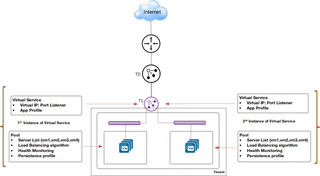
General diagram of the load balancer
A load balancer option is available on the T1 gateway.
You can create:
- Virtual Services: A virtual service is a combination of an IP address and a port that uses a single network protocol. A virtual service listens for traffic to an IP address. It processes client requests and directs valid requests to a member of the load balancer server pool.
- Pools: A server pool is a group of one or more servers that you configure to run the same application and ensure high availability.
- Application Profiles: Application profiles determine the behavior of virtual services based on the type of application. Types of application profiles, such as HTTP, HTTPS, L4 TCP, L4 UDP, L4 TLS, can be used.
External and Internal Load Balancer
Depending on configuration needs, you can deploy the load balancer for internal and external applications.
In this example, Pool 1 runs an outward-facing application. The servers in Pool 1 access Pool 2, which runs an inward-facing application.

Upgrade
Cloud Avenue Shared: Number of Virtual Services
If you need to create additional load balancers beyond those assigned by default when opening your tenant, you can request an additional virtual services pack.
Cloud Avenue Private: Service Unit Counting (cores)
You can request an upgrade for the load balancer engine, meaning an increase in the number of engine cores (vCPU). By default, your load balancer engine is provisioned with the number of cores specified in your order form.
User Interface Options
Cloud Avenue Shared
If you have the Cloud Avenue Shared offer, you will have by default the vCloud Director tenant management portal as a self-service interface to create/manage virtual services with associated advanced features such as HTTP Policy or WAF.
Cloud Avenue Priate
If you have the Cloud Avenue Private offer, the available interface types depend on the options you have chosen, especially if you have not selected the vCloud Director tenant management portal option:
- If you have opted for vCloud Director, you will use it to create/manage virtual services with associated advanced functions such as HTTP Policy, WAF.
- If you have not opted for vCloud Director, you will have access to the NSX Advanced Load Balancer interface to create/manage virtual services in your tenant with associated advanced features such as HTTP Policy, WAF.
Advanced Features
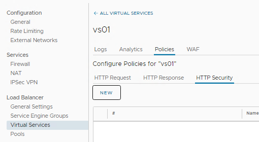
HTTP policy
The HTTP policies of virtual services allow controlling security, client request attributes, and application response attributes.
A virtual service policy consists of match criteria and actions that function similarly to an if-then statement. If match criteria are met, defined actions are performed.
HTTP policy rules can be configured only to a layer-7 virtual service.
- HTTP Request Rules : Use HTTP request rules to modify requests before they are either forwarded to the application, used as a basis for content switching, or discarded.
- HTTP Response Rules : Use HTTP response rules to evaluate and modify the response and response attributes that the application returns.
- HTTP Security Rules : Use HTTP security rules to configure allowing or denying certain requests, to close the TCP connection, to redirect a request to HTTPS, or to apply a rate limit
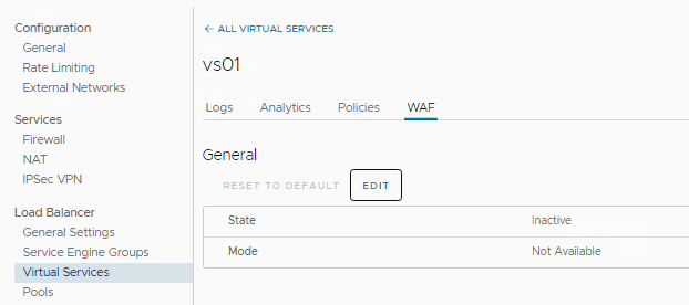
Web Application Firewall (WAF)
The Web Application Firewall (WAF) can be enabled for a virtual service. Two WAF modes are available: Detection Mode and Enforcement Mode.
Detection Mode:
The WAF policy evaluates and processes the incoming request, but does not perform a blocking action. A log entry is created when the request is flagged.
Enforcement Mode:
The WAF policy evaluates the request and blocks the request based on the specified rules. The corresponding log entry is marked as REJECTED
QoS appliance
Overview
The quality of service, or QoS designates a mechanism making it possible to ensure the prioritization of the most important flows in a limited bandwidth. Customers who use their BVPN access to connect to their information system hosted on Cloud Avenue may encounter contention problems when the bandwidth subscribed to the site’s BVPN access is limited. “Real-time” type applications, most of the time communication applications (telephony over IP, videoconferencing, etc.), will suffer greatly from this contention and will have a significant drop in sound and image quality.
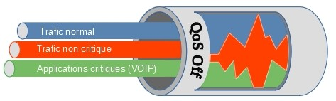
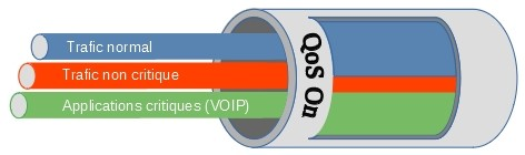
To avoid this, Quality of Service mechanisms must be put in place, in order to prioritize the most critical flows.
Implementation
A QoS Appliance is deployed between the T0 VRF and the BVPN Galerie network access router. Outgoing flows are filtered and prioritized based on the DSCP marking of network frames.
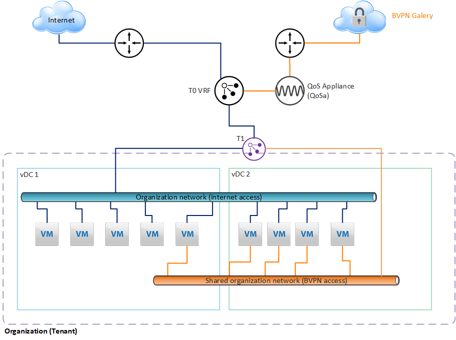
The QoS Appliance is deployed in HA (2 VMs in a cluster), hosted in the Service Zone and managed by Cloud Avenue.
Prerequisites
Critical applications must mark flows according to the DSCP standard. For more information on DSCP, visit this page:
https://fr.wikipedia.org/wiki/Differentiated_Services_Code_Point
Set up
The order is made from the Customer Area, using a change request for the moment.
Billing
The QoS Appliance (QoSa) is deployed on demand, and is billed monthly, depending on the model chosen. There are three models:
| QoSa model | Max throughput of the appliance |
| Small |
50 Mbps
|
| Large | 500 Mbps |
| X-Large | 2 Gbps |
See the tariff sheet for the price.